
To start with, from this new pack of parts, I'm gonna go ahead and assemble the framework pieces and attach the hull plates that came with them.


Oh yes. Starting to get some of the body of the Falcon.

Next up is priming the wall pieces for the hall set.
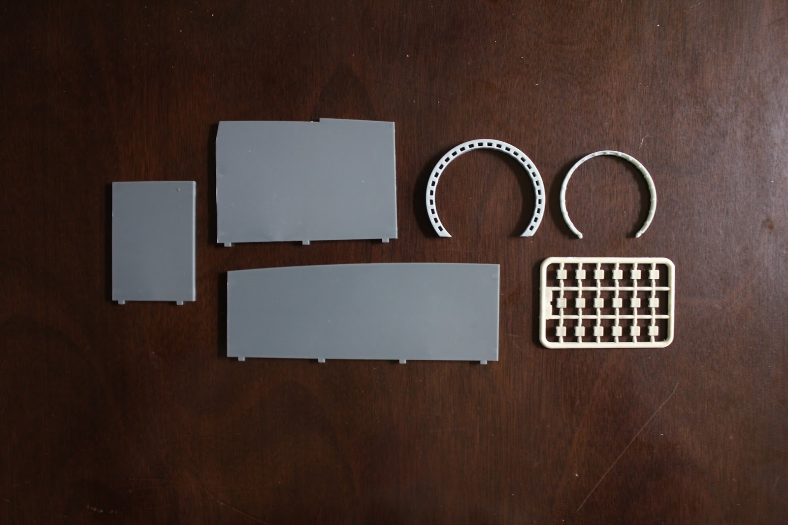
Then painting to match the rest of the hall.

I'll begin with assembling the archway. There are 18 cushions to be removed from the spru. All of which have little bits left after cutting away.

So sanding needs to be done on all 18 of the cushions.

Tiny little suckers.


And there we have the completed inner portion of the archway.


Now before inserting the inner arch into the outer arch, I have noticed that the modeling of this is slightly off. In the film, the square holes in the arch alternate between 1 long hole, 2 short, 1 long, etc. So, as Han said himself "I've made a lot of special modifications myself".

So I've decided to cut away every other set and make it like the film.

And there you have it.

My next step to make it more realistic and accurate is to route out an area in the back of the arch where I can put wires inside to look like hoses and such.

So with the Dremel, I route out a wire holding.


Then insert the inner arch and glue some wires inside my routed area.

Now, if you remember back in Pt. 9 I cut out holes in the wall and made little boxes out of styrene to go behind. Until now, those have remained unfinished. I found an old model kit upstairs of Boba Fett's Slave One ship. In the parts I found some small pieces that I cut out and have glued inside my box to look like circuits and such.

Then painted black, dry brushed with silver....

Glued in a couple of wires.....

Another piece for the lower cut out....

And there you have the cutouts complete.

Next up is the cabling and hoses on the wall. The pieces come modeled in the correct color, but.....

the actual hoses in the film have red and black stripes on them. So masked....

And painted...

And attached to the wall. BUT, the right white hose that runs down to the ground actually curves and runs into the cutout that I made in the wall. There are also other hoses and tubes on the wall as well.

So with a heat gun, I was able to re-shape the right hose to go inside my cutout. Then with some other wire I had, made a black hose run out of the top of the arch and another hose drop down and run under the circuitry on the left.

The next wall piece is the wall which goes behind the navigation console, which is full of 45+ fibers and and LED at this point. So I've had to cut out part of the floor and wall to accommodate my lighting.


And there we have the lighting running out through my cutouts.

Lookin good.

A bunch of fibers.

Now, when I assembled the bench for the game table, I left off the far end of rear cushions that came with the model, because in the film, there are no rear cushions (seen in second picture below). Just the bench seat on the far end. But, in keeping the rear cushions off, the back of the bench was slightly odd. In the film there is actually a little backing with texture, and maybe buttons. Not sure. So I made a backing out of some styrene.

This will be placed over the back portion of the left side of the bench

like so. Primed....

A little putty to make it more seamless...

Some little pieces of styrene added for texture and greeblies and then painted.


And here we have photos of the hall as it stands at the moment, with full lighting.


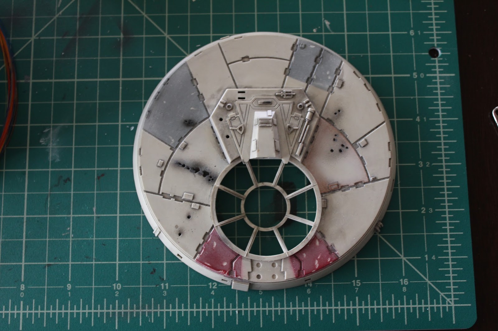
Back in Pt. 6, I painted the laser turret section of the Falcon. Well, another minor discrepancy I've discovered with the kit is the window frame. This is how the frame came with the kit.

However, the frame is actually positioned wrong. So I cut around the inside of the frame and popped it out to rotate to be accurate.

And this is the way the frame is supposed to be positioned. Don't you all just feel so much better now?
And the last thing I've done with the latest parts is add the light leak tape to the inside of the cockpit to keep light from shining through the plastic itself.

So there we have the end of Pt. 11 and parts 9-12. So now I have to wait for my next set of parts to arrive in the beginning of July. So until then, enjoy the beginning of summer.
MUCH MORE TO COME.....